Buildingo
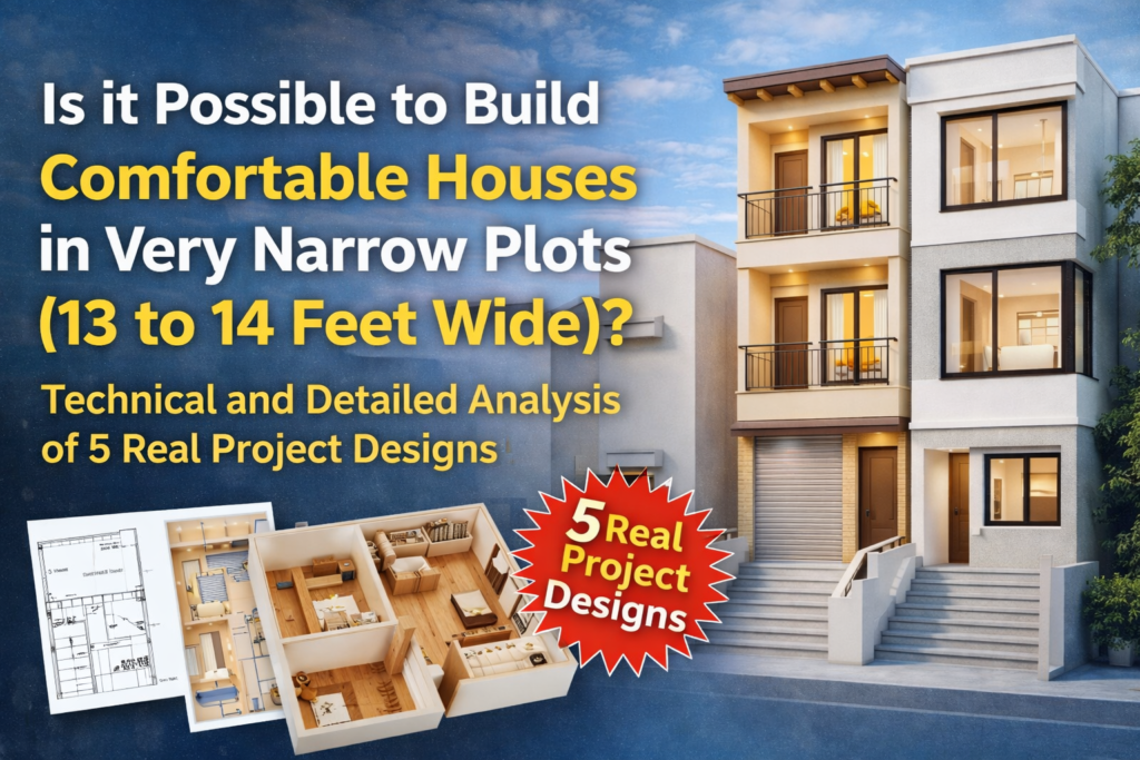
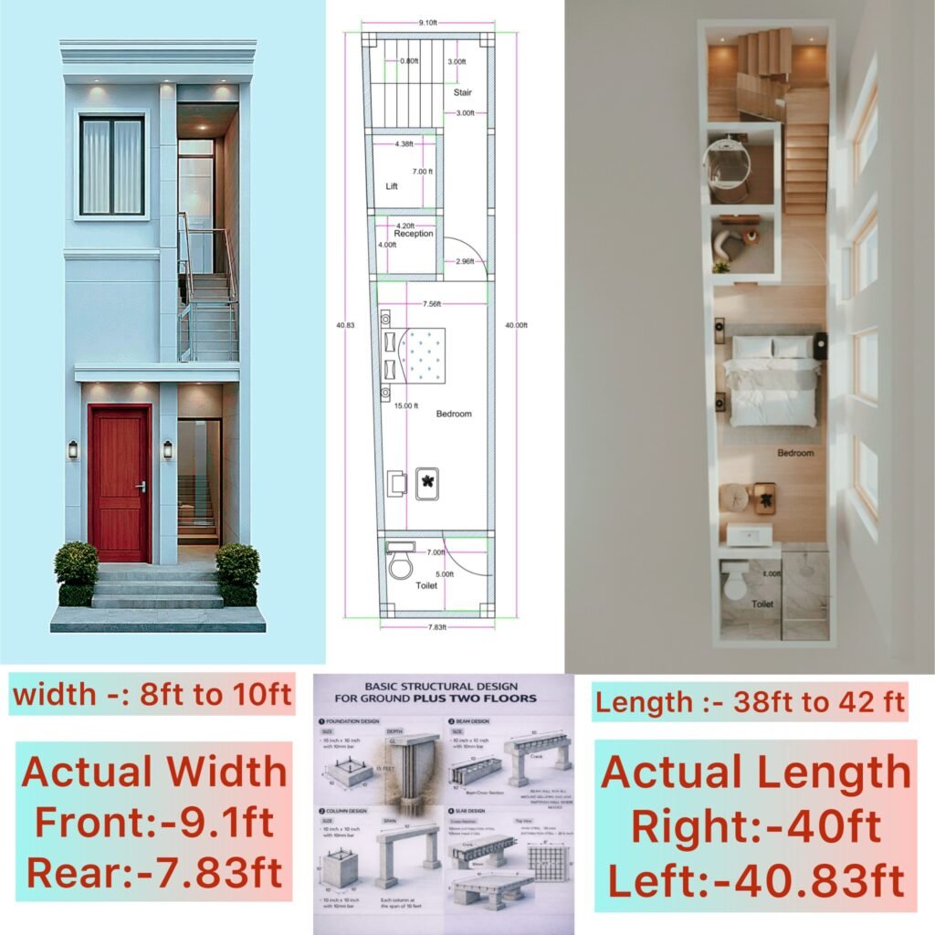
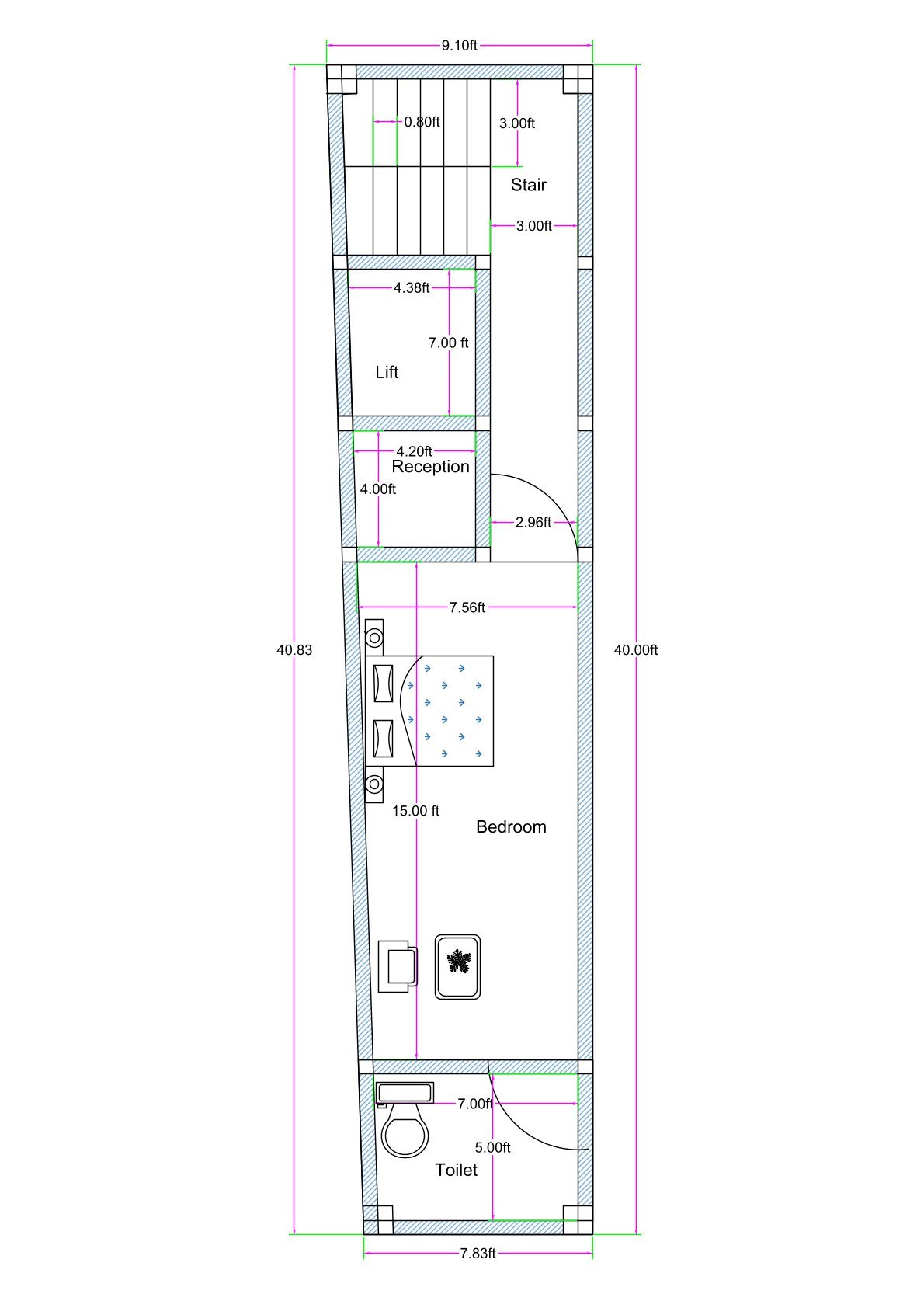
Designing on a narrow and slightly trapezoidal plot is always a challenge, especially when the front width is 9.1 feet, the rear width reduces to 7.83 feet, the left depth is 40.83 feet, and the right depth is 40 feet. This irregular geometry demands precision in planning, structural balance, and space optimization.
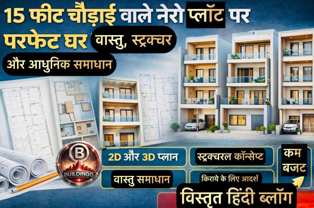
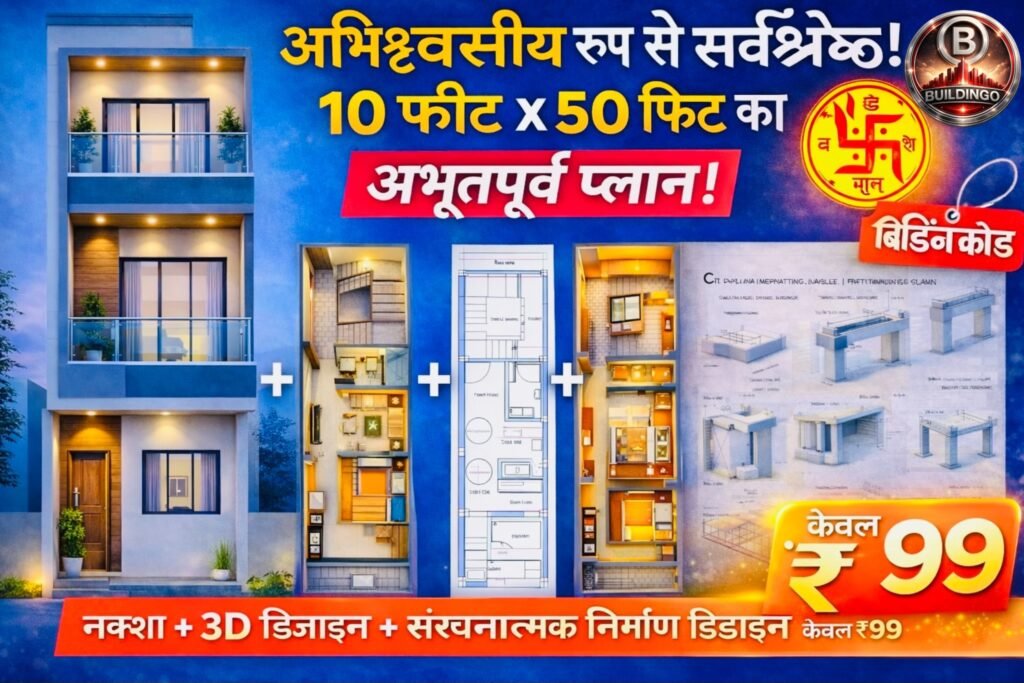
In this blog, I am explaining a fully planned Ground Plus Two (G+2) residential structure designed specifically for such compact urban plots. The design includes a 2D dimensioned floor plan, a 3D interior layout, a 3D front elevation, and a basic structural framework suitable for safe G+2 construction.
Let’s break down every component technically and practically.
1. Understanding the Plot Geometry
The plot is not rectangular. It slightly tapers toward the rear:
- Front Width: 9.1 ft
- Rear Width: 7.83 ft
- Left Side Length: 40.83 ft
- Right Side Length: 40 ft
This 3-inch variation in depth and more than 1-foot variation in width require wall alignment adjustments and careful structural grid placement. The structural design must follow the narrower rear dimension to avoid cantilever stress imbalance.
Because of the tapering rear, internal space planning follows a linear zoning concept, where functions are arranged sequentially rather than side-by-side.
This compact layout is part of our full 10-drawing residential project.
Explore the master guide here → [Link]
2. Functional Zoning – Logical Space Flow
The planning follows a straight-line functional sequence from front to rear:
Entrance and Staircase Zone
Near the front, the main entrance is positioned adjacent to the staircase. The staircase is designed efficiently within the narrow width while maintaining comfortable tread and riser proportions.
The staircase placement near the entrance serves three purposes:
- Independent vertical circulation for upper floors.
- Structural load concentration at the front grid.
- Easy rental flexibility for upper floors in future.
The staircase also visually enhances the 3D elevation, as seen in the rendered front view.
Lift Provision (Compact Vertical Mobility)
Behind the staircase, a small lift shaft is incorporated. In a narrow plot like this, lift planning must be extremely compact. The shaft is positioned centrally within the structural grid to distribute loads uniformly down to the foundation.
Providing lift provision in a 9-foot-wide plot reflects forward-thinking urban planning. Even if installed later, the shaft ensures future adaptability.
Reception Area
Moving inward, we reach a compact reception space. In narrow plots, reception acts as a transition zone between circulation (stairs/lift) and private space (bedroom).
The width restriction demands minimal furniture and wall-mounted elements. Proper lighting and light color materials enhance perceived spaciousness.
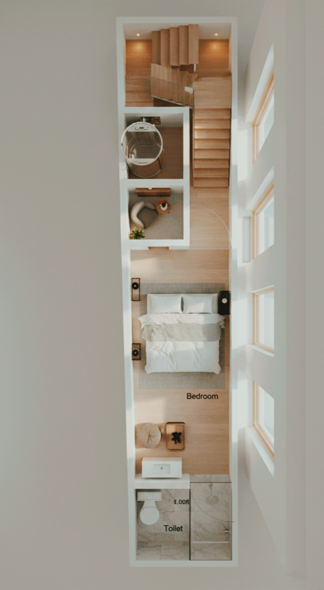
Bedroom (Office-Type Configuration)
The central and largest usable portion of the plot is allocated to a multi-functional bedroom. Due to compact width, furniture placement follows longitudinal orientation.
This bedroom can function as:
- A residential sleeping space
- A home office
- A studio room
The 3D plan clearly shows how bed placement and side furniture are arranged without blocking circulation.
The longitudinal planning maximizes usable walking space even within a 7.8 to 9 ft width constraint.
Attached Toilet (Rear Section)
At the rear end, a 5 ft x 7 ft toilet is provided. The rear narrowing of the plot is efficiently utilized here.
The toilet location at the rear is technically sound because:
- Plumbing lines can run vertically for upper floors.
- Ventilation shaft can be aligned at the rear.
- Structural beams can frame the wet area separately.
Wet areas at the back reduce moisture risks to front structural components.
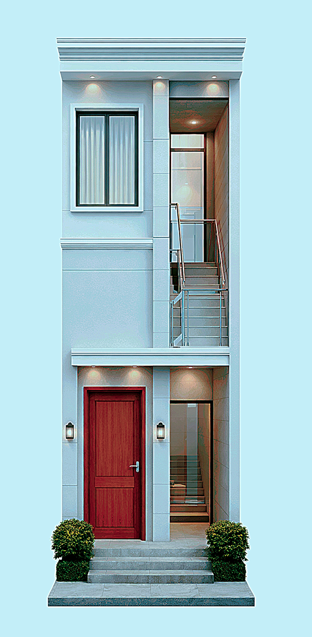
3. 3D Elevation – Architectural Character on a Narrow Plot
The 3D elevation demonstrates how even a 9-foot frontage can look elegant and premium.
Key elevation elements:
- Vertical lines to emphasize height.
- Balanced window positioning.
- Modern railing detailing.
- Minimalistic façade projection.
The elevation avoids heavy cantilevers due to structural limitations of narrow plots. Instead, it uses clean geometry and material contrast for aesthetic appeal.
The staircase glazing adds visual transparency, reducing façade heaviness.
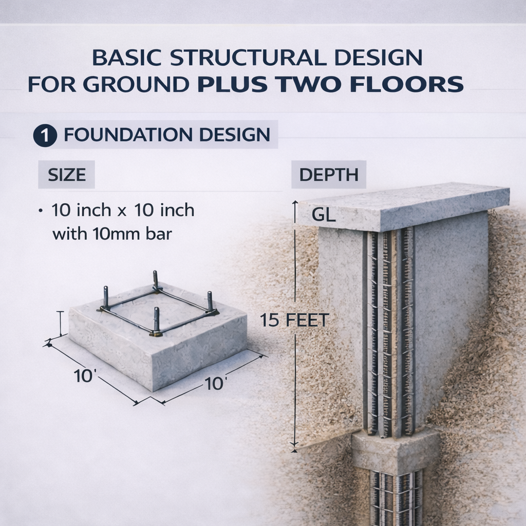
4. Structural Design for G+2 – Technical Breakdown
Now let’s discuss the most important part: Structural Safety.
This structure is designed for Ground Plus Two floors using the following basic structural guidelines:
Foundation Design
- 10 inches x 10 inches column base
- Depth: 10 feet below ground level
- Acts similar to a mini pile foundation
In narrow plots, deeper foundation is preferred because:
- Load concentration is higher.
- Soil pressure must be distributed vertically.
- Adjacent building loads may influence soil behavior.
The 10-foot depth ensures stability and reduces differential settlement.
Column Design
- 10 inches x 10 inches RCC column
- Reinforcement: 10 mm bars
Column size is maintained uniformly for vertical load continuity. Since the width is limited, increasing column size excessively would reduce usable space. Therefore, structural efficiency is achieved by maintaining proper reinforcement rather than increasing dimension unnecessarily.
Columns are aligned vertically from foundation to terrace without offset to avoid eccentric loading.
Beam Design
- 10 inches x 10 inches beams
- Continuous around perimeter and partition walls
Beams are designed to tie all columns together, forming a rigid frame structure.
In narrow buildings:
- Beam continuity is critical.
- Torsion effects must be minimized.
- Edge beams prevent lateral sway.
The beams also frame the staircase opening and lift shaft carefully.
Slab Design
- Thickness: 4 to 5 inches
- Main Steel: 10 mm
- Distribution Steel: 8 mm
Because spans are small (due to narrow width), slab thickness can remain controlled within 4–5 inches.
The steel layout ensures:
- Bending resistance in main direction.
- Crack control in secondary direction.
- Load transfer to beams efficiently.
Partition Walls
- Thickness: 5 inches
Using 5-inch partition walls reduces dead load while maintaining sufficient stiffness.
5. Why This Design Works Technically
This design succeeds because:
- It respects the trapezoidal geometry.
- Structural grid follows narrower rear dimension.
- Vertical loads are aligned straight.
- Wet areas are stacked for plumbing efficiency.
- Staircase and lift create a central rigid core.
Even on a compact 9-foot frontage, the building can safely rise to G+2 with proper reinforcement detailing.
6. Practical Urban Benefits
Such compact designs are ideal for:
- Dense city lanes.
- Budget-conscious construction.
- Rental model housing.
- Mixed-use small offices.
With proper execution, this narrow plot does not feel congested internally due to longitudinal zoning and controlled structural proportions.

Conclusion
This 9.1 ft to 7.83 ft trapezoidal plot proves that intelligent planning and structural discipline can convert a constrained urban space into a safe and elegant G+2 home.
From 2D dimensional clarity to 3D visualization and structural detailing, every component is aligned toward practicality and stability.
Compact does not mean compromised.
With correct column sizing, beam framing, slab thickness, and functional sequencing, even a 9-foot-wide frontage can deliver a beautiful and structurally sound multi-storey residence.